The Master Principle of EM Overunity and
the
|
|
1 |
∂ |
||
|
div (S+S')+ |
— |
— | (B2 + E2) + cE(i + i') = 0 [4] |
|
8π |
∂t |
where
|
c |
||
|
S = |
— | (E x B) |
|
4π |
is the Poynting vector, and S’ is any vector field whose divergence vanishes; div(S) is the rate at which the stored field energy is diminishing in the unit volume in question due to a net outward flow of energy;
|
1 |
∂ |
|
|
— |
— | (B2 + E2) |
|
8π |
∂t |
is the rate at which the amount of stored field energy in the unit volume is changing, and the expression cE(i+i’) is the rate at which the electric field does work on all the moving charges, in unit volume, losing energy at that rate. Further, i represents the ordinary gross macroscopic conduction current while i’ represents the net microscopic current (within the molecules or within the atoms).
As Jackson points out, the curl of any vector field can be added to S, since the divergence of the curl vanishes.[55]
In the theoretical case, EM energy that flows along (outside) a wire in an open (i.e., dq/dt-blocked) electric circuit is just such a divergence-free field.[56] If we utilize a multivalued potential, then in the multivalued "jump" region there is just a sudden injection of excess S-flow due to the injection of a different equipotential. Consequently an “open circuit” — i.e., one in which the current dq/dt is blocked — may still pass Poynting EM energy since all the “energy flow” in a circuit exists in the flow of voltage (potential),[57] and voltage may flow without concomitant current. In fact, rigorously the EM energy flowing “in” an electrical circuit does not flow through the wire, but outside it.[58] The wire serves as a sort of waveguide or railroad track for the energy flow outside. Obviously, if we block the current dq/dt in the wire, we shall block the expenditure of EM energy as work in that blocked current loop. However, we can still pass the Poynting vector flows, and therefore we can still pass EM energy without any dissipation of it in that current loop. Since no work is being performed in the current loop, no work is being done inside the source for that blocked current loop — the source being in series in that loop.
As we previously stated, it is already shown in particle physics that any electric charge is an asymmetry in the violent energy exchange between the vacuum and the charge. Every charge is therefore either a source or a sink. Any dipole is automatically a source on one end and a sink on the other, freely extracting and gating a circulation of excess energy from the vacuum to 3-space and back to the vacuum. This is true for both an electric dipole and a magnetic dipole.
To build a free energy EM source, we do not have to discover how to extract and gate excess energy from the vacuum. Every source we have ever built is already doing just that. We only have to discover how to cease using half the collected energy in a circuit to do work on the internal separation of charges that makes the dipole itself, thereby destroying the source dipole. In other words, we only need to cease "killing" our free energy sources already available in every EM circuit and system.
My colleagues and I have shown how to do it with electrical circuits and now with a special magnetic circuit called the motionless electromagnetic generator (MEG). Johnson has shown how to do it with a motor comprised only of permanent magnets in both the stator and the rotor. The Wankel engine has shown how to do it by using a single electromagnet in a narrow sector of the stator, and the rest of the stator comprised of permanent magnets while the rotor is composed of permanent magnets. Kawai has shown how to do it beautifully in a motor with the rotor comprised of permanent magnets and the stator comprised of electromagnets.[59] All these various approaches are in fact applications of the same master overunity principle advanced in this paper. All utilized one or more methods of performing regauging by means of a multivalued potential (MVP) or a pseudo-MVP (i.e., an emulated MVP).
Here is a very simple but profound truth. The very notion of a dipole already implies dq/dt blocking. That is, even though the two charges are attracting each other, they are not moving together. This automatically produces a flow of potential and energy.
Also, contrary to present electrodynamics practice, a potential — simple electrostatic voltage — is not at all "static" in and of itself. Its intensity at a fixed point is "static" in that it is not changing in intensity! The potential is no more static than is the steady light from a perfect light bulb. Internally, a "static" potential is comprised of bidirectional EM waves, arranged in precisely coupled pairs, as shown by Whittaker in 1903. If voltage truly were "static," it could never flow. A quiet river may have a static magnitude at a given point or points, but no one would dream of suggesting that the river itself was static. The magnitude of the potential is not the potential itself! It is just one attribute of the potential. A static magnitude of the potential at each and every point it occupies, does not tell one anything at all as to what the potential itself actually is, or what it is doing.
Because of its hidden dynamic composition, the electrostatic scalar voltage will "flow" from the charged end of a dipole if we extend the charges available to that end from point charges to line charges; i.e., if we simply "morph and stretch out" the end charges. If the resulting circuit is open, the voltage will still flow to the ends, even though (for ideal conductors) no current dq/dt flows. And we already know from Poynting theory that a real flow of EM energy of form S = ExH continually flows along the conductors.
The primary electrical power source (i.e., the dipole) is not dissipated whenever only loss-free field energy density S is extracted from it. Any source of potential is a priori a free source of EM field energy density — the open-circuit potential and the S flows “for free” and at no dissipation to the source. The energy is extracted from the vacuum and flows along the blocked (“open”) circuit wires as lossless flow of potential onto collectors (such as electron capacitors). Applying this potential to trapped charges in a capacitive collector allows energy to be extracted from the vacuum by the source, and furnished to the collector as excess field energy on the blocked electrical charges of the collector.
So here we have extracted a principle: When the dq/dt current is blocked in a conductor, the conductor can still pass S-flow and the flow of potential. The current dq/dt is a response of the circuit to the free EM energy flow impacting the Drude electrons.
With dq/dt blocked, if voltage (potential) is varied across a coil, normal magnetic field B is created in the coil by the changing E-field. Energy is thus stored in the coil in the form of ordinary B-field.[60] It does not require moving charges dq/dt to create a magnetic field. As is well known, in the vacuum the magnetic field is continually created by the varying E-field, and there are no observable charges q present nor is any dq/dt present.[61]
Further, if the storage coil is the primary of a transformer, a correspondingly induced alternating B-field is created in the secondary in normal fashion as the B-field in the primary is produced in AC fashion. In short, field energy density flows from the vacuum through the charge-blocked primary and across to the secondary without work.[62] In the external circuit on the secondary side, charges need not be blocked. In that case the excess field energy density and emf cumulated in the secondary couples to the conduction electrons in the secondary circuit. In the secondary closed current loop, the coupling-in (shuttling in) of excess voltage and emf activates the circuit, and drives electrons around the secondary current loop, passing through the load and powering it in normal fashion.[63] None of this load discharge current passes back through the original source; hence no dissipation of the source occurs, even though the load is powered. So the charge-blocked and energy-shuttling system in this case has become a continuous “free power” system, powering a load without exhausting the primary power source.
In this way the source will power a load indefinitely. Energy is conserved, but not work. There is no law of physics that requires work to be conserved! The laws of physics and thermodynamics are not violated. The dipolar system is an open system, receiving and extracting usable EM energy from a recognized source (the virtual photon flux of the quantum mechanical vacuum).[64] The continual bidirectional virtual energy exchange between the vacuum and charged particles in the dipolar separation of charges in the electrical power source provides a continual inflow and outflow of vacuum energy.[65] By charge blocking, this exchange energy flux (potential) is gated by the circuit wiring (“waveguides”) and moved down the circuit without any work being done in the source antenna to dissipate its separation of charges. In the external circuit the energy density is collected as a finite amount of energy in a finite collector (a coil or a capacitor whose dielectric cannot undergo strain). By switching the capacitive collector or by inductive transformer coupling, the collected free energy is shuttled to a separate circuit and regauges that receiving circuit. The excess energy now stored in the regauged receiving circuit is then discharged normally in the load. In either case the “energy collection” circuit and the “load discharge” circuit are in separately isolated current loops. The result is a legitimate open system capable of overunity coefficient of performance (COP), comparable to a heat pump.
With the forthcoming closed-loop (self-powering) systems, the applications to portable systems (power sources, laptops, lights, power tools, radios, TVs, mobile vehicles, etc.) are enormous. A single auto battery will be utilized with a charge-blocking/energy shuttling system to power a large, agile automobile or truck. Once in operation, the battery will be switched out of the circuit and the system will be self-powered. It will also be non-polluting. By dramatically reducing the heating problem, eliminating the need for a connection to an external power source, and indefinitely extending the “power on” time, these mobile systems will become dominant.
It appears that the Japanese are already poised to massively launch this revolution as early as October 1996. [Added]: As previously stated, this would have indeed happened, and my colleagues and I would have placed the Kawai system on the market ourselves, had not Japanese overunity systems been seized and kept off the market by the Yakuza.1
We now examine the
Poynting flow when operating a circuit in a charge-blocking fashion. We
start by examining the standard Poynting theory for loss of field energy
stored in a unit volume, as shown in equation [4]. We again reproduce
the equation here for ease in reading.
|
1 |
∂ |
||
|
div (S+S')+ |
— |
— | (B2 + E2) + cE(i + i') = 0 [4a] |
|
8π |
∂t |
The Poynting theory of equation [4] deals with the loss of EM field energy from a unit volume. It states that the field energy in a unity volume of interest can be lost by three methods, as previously explained. The three loss terms in equation [4] do not overtly allow a flow of energy into the unit volume, except by the divergence loss term becoming negative and hence a convergence, the field energy loss term becoming negative and hence an inflow, and the work term for translation of charged particles becoming negative, in which case the particles are giving up field energy to the volume.
So as far as electrical circuits are concerned, the standard Poynting equation is a very awkward expression, primarily adapted to deal only with energy flow out of unit volume and through unit area thereof. However, this shortcoming can be remedied by rewriting the terms so that all expressions deal both with field energy loss and field energy gain. For clarity, we use the following word equation shown in Figure 6 for a change in the field energy stored in a unit volume:
Figure 6 shows the word equation used to set up the necessary mathematical relationships. One simply starts with an initial amount of field energy in the unit volume, then adds all gains and subtracts all losses, to arrive at the final field energy stored in the unit volume. By definition, we take the convention that the algebraic sign of gains is positive, and the sign of losses is negative.
Figure 7 shows the word equation used to set up the necessary rates of gains or losses of field energy in a unit volume. By integrating each term over a definite time t, that term becomes an amount of change after that time t has elapsed. By then adding the initial EM energy, the final remaining amount of energy in the unit volume can be ascertained as was shown in Figure 6.
We take the initial
field energy stored in the unit volume of interest as
|
1 |
|
|
— |
(B02 + E02) [5] |
|
8π |
where the subscript zero means initial. We take the amount remaining after the change as
|
1 |
|
|
— |
(Bf2 + Ef2) [6] |
|
8π |
where the subscript f means final. The amount gained by inflow is the time integral of the instantaneous rate of inflow, or
|
∫t |
1 |
∂ |
|
|
— |
— | (Bin2 + Ein2) [7] | |
|
8π |
∂t |
The amount lost by outflow is the time integral of the instantaneous rate of outflow, or
|
∫t |
1 |
∂ |
|
|
— |
— | (Bout2 + Eout2) [8] | |
|
8π |
∂t |
We shall assume there is no field divergence loss, since the circuitry wires act as waveguides and energy transport flow is confined to the waveguides. The loss in performing work to translate conduction charges is given by the time integral of the instantaneous rate of loss for conduction charge translation, which is
∫t cE ∙ (i + i') [9]
Note that, if we do not consider the internal atomic or molecular charge movement, this reduces to ∫t cE ∙ (i + i'). Further, if we block the charge flow i, the remainder of the term reduces to zero.
So with charge blocking, the instantaneous rate of change of the field energy stored in the unit volume is just
|
1 |
∂ |
1 |
∂ |
1 |
∂ |
|||
|
— |
— | (B2 + E2) = | — |
— |
(Bin2 + Ein2) – |
— |
— |
(Bout2 + Eout2) [10] |
|
8π |
∂t |
8π |
∂t |
8π |
∂t |
In other words, the situation has reduced to pure energy transport without loss.[66] Also, among other things this immediately proves that use of dq/dt-blocking accomplishes regauging of the downstream receiving circuit.
We note that the two terms on the right side of equation [10] need not be equal. If the rightmost term is largest, then the stored energy is discharging. If the leftmost term on the right side of equation [10] is the larger, then the stored energy is increasing.
When we regauge the system by injection of excess potential energy, then the leftmost term on the right side of equation [10] is much larger, and the stored energy of the system is rapidly increasing. Integrated over the very small but finite "jump" time dt, equation [10] then gives the total regauging energy freely added to the system.
We further point out that equation [10] applies to either an electrical device or a magnetic device, or a combination. If the current-free field energy is being stored in an inductive collector, the B-field increase is significant. If the current-free field energy is being stored in a capacitive collector, the E-field increase is significant.
With dq/dt-blocking, one may conduct work-free energy flow along electrical circuits without losses. This energy flow is in the form of d/dt, or simply put, dV/dt and it automatically involves S-flow and regauging of the receiving circuitry. It is directly comparable to the flow of open-circuit voltage down an ideal transmission line with an open circuit. From the standpoint of gauge field theory, it also involves a change of gauge in the receiving parts of the system, as we stated previously.
What is actually being “conducted” is the change in the rate of virtual photon exchange between the vacuum and charged particles. If the charges q do not translate (i.e., if their longitudinal movements are blocked), then Ñ (with respect to ground reference) is built up on each of them. That is, each of them is potentialized to the new potential. In this manner the energy coming from the vacuum exchange may be captured and stored on trapped/blocked charges q as excess E-fields between the potentialized charges and the ground line, and hence as excess field energy. This is a capacitive-type storage. Taking only voltage from the power source does not diminish its ability to continue to furnish such voltage. Adding this voltage V to trapped charges q produces an energy storage on those charges of Vq. The collector with its stored energy may then be switched out of the collection circuit and across a load, where it is discharged normally through the load in a separate circuit. The collector can then be switched back to the blocking/collection circuit to collect additional free energy. Obviously this modality allows overunity COP.
We have previously explained the collection and shuttling of excess free energy S-flow using transformer coupling, and step-up transformers for amplification. Coverage for these areas was included in our patent application of February 1994 and continuation of May 1994. Additional coverage was included in our patent application of June 1995 and our provisional patent application of July 1995.
This current-free energy flow for regauging the downstream circuitry does not dissipate the power source furnishing the potential and S-flow. One can draw nondiverging field energy from any source of potential indefinitely, without dropping the potential of the source. As we stated, this is because internally the "electrostatic" scalar potential is a bidirectional flow process, not a “static” thing as it is treated in electrostatics.[67] In fact, any scalar EM potential may be considered as an infinite sum of a harmonic series of hidden bidirectional EM wavepairs, where each pair consists of the wave and its phase conjugate (time-reversed) replica wave.[68]
Via the distortion correction theorem[69] of nonlinear optics, a true phase conjugate wave will precisely superpose spatially with its stimulus wave, but the two are a priori antiposed in the time dimension. This means that the individual moving EM force components of the two waves are seen to “cancel” electromagnetically, insofar as the external observer is concerned, but their energy components remain and add.[70]
Hence the special “standing wave” that results from this novel superposition is a true electrogravitational standing wave of the variation in virtual photon flux density — and hence in the local stress energy density — of the vacuum/spacetime itself. It is well-known in general relativity that all potentials are gravitational in that they contain trapped energy, and in the modern view it is energy that is gravitational a priori. The Whittaker mechanism, however, reveals the nature of the trapped EM energy in the potential, as well as the nature of the trapping mechanism.[71] Sweet and Bearden have previously released the results of a successful antigravity experiment using this aspect.[72]
In our 1994 patent application and continuation, we showed methodologies and embodiments of the fundamental process for use of charge blocking to obtain overunity electrical power systems. Our fundamental claims apply to the use of any charge-blocking mechanism, such as use of a Fogal charge-blocking semiconductor, to achieve overunity by energy (potential) storage and shuttling to achieve overunity coefficient of performance (COP). Disclosure of part of the mechanisms and embodiments were made in February 1993,[73] and additional disclosure presentations were made at a scientific symposium in May 1994.[74] Since then our additional patent applications have materially extended the theory, the processes utilized, and the typical embodiments.[75]
See Figure 8 for the principle of the magnetic Wankel engine.[76] Here a set of permanent magnets, each at an angle to the various radial lines of the device, comprises a slightly widening spiral stator that is "almost" circular but not quite. A circular rotor is mounted inside this spiral stator. An end gap exists in the stator as shown, so that the stator is not a complete closed ring. The direction of rotation for the rotor is clockwise as shown. For demonstration of the principle, the beginning air gap is 0.1 mm and the ending air gap is 5 mm.
A permanent magnet is mounted along the perimeter of an angular sector of the rotor. It is magnetized, say, with the north pole facing radially outwards, and the south pole facing radially inside. In the stator, the permanent magnet north poles are facing radially in toward the rotor, but at an angle, and the south poles are facing radially outside but at an angle.
Thus tangentially the north pole of the rotor is in a nonlinear magnetic field, and it will experience a clockwise force and acceleration from position 1 (where the air gap is the minimum) to position 2 (where the air gap reaches maximum).
If this were all there was to it, the magnetic Wankel motor would not be overunity because the tangential field is conservative. When the rotor crossed the end gap in the stator between point 2 and point 1, very sharp and dynamic braking work would be done back upon the rotor magnet by the field of the stator magnets at point 1. This braking work would precisely equal the amount of dynamic acceleration work that was done in accelerating the rotor magnet from position 1 to position 2, in accordance with equation [1] shown previously. For an absolutely frictionless machine with no losses, the coefficient of performance (COP) would be 1.0. Since any real machine will have at least some friction and drag, the actual COP would be less than 1.0.
Let us now utilize the notion of the magnetostatic scalar potential to examine a new situation in the end gap.
Technically, let us regard a single unit north pole in the rotor, going from position 1 to position 2 (the acceleration cycle, where the engine will deliver shaft horsepower against a load), and then from position 2 to position 1 (where the magnetostatic scalar potential must be regauged to equal or exceed the potential at position 1, in order for the rotor to continue unabated or even further accelerate. I.e., in the separation gap, a regauging operation must be done so that the "stator to inner" potential is increased equal to or exceeding the "stator to inner" potential of position 1. In normal machines, the regauging part of the cycle is always where the design engineer forcibly input energy from outside the system to do physical work on the machine to forcibly "reset" its energy storage back to initial conditions. In the past engineers have automatically assumed COP<1.0 without exception, since their forcible RESET work was always equal to the maximum theoretical energy output to the load during the motor part of the cycle from point 1 to point 2.
So we simply must perform the regauging or RESET of the system's energy storage, without performing tangential "drag" work on the rotor. For that purpose, an electromagnet is utilized to fill the end gap in the stator, arranged so that when it is activated its north pole will face radially inward. A small current activates the coil weakly, through a distributor with breaker points. At the proper timing (i.e., when the rotor is directly opposite the electromagnet pole piece, a set of ignition points is sharply broken in the circuit with the coil of the electromagnet. Momentarily, a very high potential will appear at the end of the coil as the collapsing field is highly amplified and trying to sustain the previous current in its previous direction. The end result is the formation of a strong magnetostatic scalar potential (pole), of north polarity, on the stator pole piece facing the rotor. Note that no radial work can be done on either the stator pole piece or the rotor by this high potential, because they cannot move radially.
The potential in the end gap is now higher than the potential at position one. Consequently a clockwise tangential force field exists between the end gap potential and the lower potential at position one. A clockwise tangential force therefore appears upon the rotor, and the rotor is accelerated and "boosted" out of the stator gap and back past point 1. At that point the electromagnet has lost its potential, but the engine has now been regauged and now is in the clockwise acceleration field of the rotor-stator permanent magnets.
In short, the rotor perceived the sudden change of magnetostatic scalar potential from the electromagnet in the stator gap as a pseudo-MVP, and the system received a sharp influx of potential energy, without work except for that lost in the electromagnet circuitry. Since that loss can be made quite nominal by conventional electronic practices, the engine permissibly provides COP>1.0. It can therefore be rigged to power itself and a load simultaneously.
Placed in an electric vehicle with necessary switching circuitry and ancillary equipment, a properly designed magnetic Wankel engine and its derivatives should be capable of starting from a single ordinary battery, then powering the vehicle agilely, powering the accessories, and recharging its own battery — all three simultaneously.
There are still some disadvantages with the Magnetic Wankel engine. First, the cobalt magnets are expensive and require arduous manufacturing in the asymmetrical configuration shown. The dynamic balancing of the engine would be critical, since the stator is nonsymmetrical and so is the rotor. Also, the single rotor sector would have to be counterbalanced on the shaft, say by another Magnetic Wankel stage in counterbalance form. It would be desirable to eliminate these difficulties and also to reduce the rather appreciable costs of such an array of magnets.
Figure 9 shows eight snapshots of the rotor advance of a typical Kawai engine, taken from Kawai's patent.[77] (Note: the Kawai patent in full, with diagrams, can be seen here). This is one end rotor/stator side of a two-rotor device, where a similar rotor/stator device is on the other end of the central shaft 11. In Figure 9A, pole piece 14 has three outward teeth 14b dispersed equally around the circumference, alternated with three notches. An end magnet 13 provides the source of flux passing through the pole piece. With the electromagnets de-energized, their core materials 16c, 16d, 16g, 16h, and 16k, 16l are shown shaded, by flux from central magnet 13 outwards through teeth 14b.
In Figure 9B, electromagnets 16a, 16e, and 16i are energized. The shaded area shows the sharp convergence of the flux from magnet 13 through pole piece 14 and the edge of teeth 14b. Since the electromagnets are magnetized in attracting mode, the rotor will experience a torque tending to widen the flux path from magnet 13 to the activated electromagnets. Thus a clockwise torque exists on the rotor, and it will start to rotate clockwise.[78] Note also that each electromagnet is operating independently of the other two.
As shown in Figure 9C, 9D, 9E, and 9F the rotation of the rotor continues clockwise, widening the connecting flux path to the three activated electromagnets. During this time the torque on the rotor is clockwise.
In Figure 9G, the flux path to the activated electromagnets is fully widened. Also, the leading edges of the three teeth are just beginning to enter the domains of the next electromagnets 16j, 16b, and 16f. This is getting symmetrical to the original position shown in Figure 9B. Consequently, the electromagnets 16i, 16a, and 16e are deactivated, and electromagnets 16j, 16b (not labeled; see Fig. 9A), and 16f are activated. Symmetrically, this regauges and resets the engine back to the original starting position in Figure 9B, but one tooth farther along. The action cycle begins anew with the next tooth 16f, as shown in Figure 9H. As can be seen, in each complete rotation of the shaft, each of the three teeth of the rotor will be regauged 12 times. So 36 total regaugings/resetting/refuelings are utilized per shaft rotation.
In each stator coil, at energization a tooth is just entering that coil. Energized in attractive mode with respect to the ring magnet around the shaft, the flux in the pole piece "jumps" from fully widened flux (and small or vanishing radial torque on the rotor) to angled and narrowed flux (with full radial clockwise torque on the rotor). As previously explained, the narrowed flux and its angle exert a clockwise accelerating tangential component of force upon the rotor. Each coil is de-energized prior to beginning to exert radial back emf (which it would do if it remained energized as the trailing edge crossed it and again narrowed the flux path). So the Kawai engine uses normal magnetic attraction to accelerate the rotor for a small distance, then regauges to zero attraction to eliminate the back-drag portion of the attractive field. It regauges to zero as the "RESET" condition.
For appreciable power and smoothness, the Kawai engine uses an extensive number of regaugings per axle rotation, being 36 times on each end, or a total of 72 for the two ends. The force field of each coil, accompanying its increased magnetostatic scalar potential, is oriented radially inward, so that radial work cannot be done by the coil on the rotor because the rotor does not translate radially. Advantage is taken of the initial clockwise acceleration force initially produced, and regauging eliminates the counterclockwise drag or "decelerating" force that would be produced without the regauging.
The major benefits of the Kawai arrangement are that (1) a large number of regaugings occurs for a single rotation of the rotor assembly, enabling high power-to-weight ratio, (2) each electromagnet is energized only when positively contributing to the clockwise torque that drives the rotor, and (3) each coil is de-energized to regauge the system during those periods when the coil would otherwise create back-drag (counterclockwise torque) if it remained energized.
So the Kawai engine delivers what it advertises: It dramatically reduces or eliminates the "back drag" from the fields of the stator electromagnets, because there are no fields activated in the electromagnets during the back-drag sectors of rotation. A conservative field cycle is one in which the back-drag is equal to the forward boost. Eliminating the back-drag portion of the cycle is a form of regauging. Note that again it was accomplished by a change in the magnetostatic scalar potential being reset to zero by the de-energized coil during the back-drag portion of an otherwise conservative cycle. The Kawai engine therefore uses regauging and nonconservative fields in order to legitimately achieve overunity operation.
Because of the numerous regaugings and back drag elimination, this engine definitely can provide a COP>1.0 if very efficient switching (such as photon-coupled switching) is utilized. Placed in an electric vehicle with necessary switching circuitry and ancillary equipment, a properly designed Kawai engine and its derivatives should be capable of starting from a single ordinary battery, then powering the vehicle agilely, powering the accessories, and recharging its own battery — all three simultaneously. And in so doing, it complies with all the laws of physics and thermodynamics.
In this paper we have briefly discussed the storage of energy in an electromagnetic circuit from a gauge-theoretic viewpoint. We have presented the multivalued potential and the pseudo-multivalued potential, and their usage in regauging the potential in the energy-storing subsystem of an EM engine. Regauging accomplishes a work-free resetting or "refueling" flow of energy in an electrical circuit, from a modified Poynting vector standpoint. In addition we have presented embodiments of the current blocking, energy storage, energy shuttling, multivalued potential (MVP), pseudo-MVP, and regauging approach for overunity electrical power systems and for room temperature superconductivity.
In addition we have explained two Japanese overunity engines, at least one of which (the Kawai engine) appears to have reached full production capability in an extremely well funded, national Japanese strategic effort lasting more than two decades.[79] The ominous implications for U.S. science and industry — and U.S. financial stability — are sobering to say the least. Beginning in model year 1997, a certain percentage of all new automobiles sold in the U.S. must be zero-polluting vehicles — i.e., electric vehicles. U.S. manufacturers are already irretrievably committed for the specific electric vehicles they will offer. These U.S. offerings will be bulky, cumbersome, largely impractical, expensive, and maintenance-intensive. They will require frequent and lengthy recharging of their huge battery packs. They will give poor performance, get very low mileage (range) between recharges, and will have only austere powered accessory systems. The manufacturers will have to either sell them or give them away somehow in order to meet their mandatory quotas.
The Japanese manufacturers appear to be poised to introduce en masse a substantial line of powerful electric engines which are overunity and self-powered, and a substantial line of powerful electric vehicles utilizing those engines. In short, those vehicles can be initiated from a single battery and self-powered from then on. They are eminently practical, unlimited in range and performance, can be large and luxurious and agile, can have full-powered accessory systems, and will probably be available in a wide range of sizes and performances.
In short, there is evidence that the Japanese have scored a great coup on the entire automotive world, and especially upon the U.S. Japanese businessmen are samurai; such is in their psyche and ingrained in their culture. For the Japanese businessmen, the financial struggle is just like any other war and any other struggle. They attack the business struggle with single-mindedness typical of the Japanese samurai warrior. They have also been strongly motivated by national need; Japan is energy-poor and literally has been at the mercy of the energy-rich nations of the world. The Japanese samurai simply have attacked their nation's energy problem like the sturdy warriors they are, and put their funds, their hearts, and their minds into it with a single purpose: winning.[80] Now we are faced with a fait accompli.
We close by emphasizing the final statements of our previous article on the Japanese overunity engines. "He that does not know history, it's been said, is doomed to repeat it. We simply must not repeat a Pearl Harbor in the overunity electrical energy field. This time the torpedoes may be too devastating for America itself to survive."
As stated in footnote 1, this time the “Pearl Harbor” in energy systems was avoided by the direct intervention of the Japanese Yakuza only a few months after writing the original article for the Virtual Times. Eerily, the timing in the original 1995 article was “right on”, and 1996 was indeed the year in which Japanese overunity systems would have been introduced to the market worldwide. When writing the article in 1995, the last thing that would have occurred to me was that Kawai would come to America to see us in Spring 1996, and contract with us to market his system worldwide. Teruo Kawai is a true gentleman, however, whom I deeply respect. I also deeply regret his misfortune.
[1] Added. I originally wrote these words in latter 1995. This marketing of the Japanese engines did not occur in 1996 after all, because the Japanese Yakuza apparently seized and has withheld Japanese overunity systems from production and world marketing in that year. The Yakuza’s suppression of the Kawai system, for example, occurred right here in Huntsville, Alabama in front of my CTEC board of directors and I, in spring of 1996. We had just reached a verbal agreement with Kawai to market his COP>1.0 motors (including the self-powering version) worldwide. Agreement occurred on a Thursday afternoon; that night a jet aircraft arrived post haste from Los Angeles. The next morning the Kawai party was in fear and trembling, and Kawai no longer controlled his own company, his invention, or his own fate. The Japanese then packed up two Kawai engines shipped in here and departed, and that was that.
[2] Tom Bearden, "A Direct 'Free Energy' Method," 1980. Internal private personal paper at the time, but long since unrestricted.
[3] T. E. Bearden, "On Rotary Permanent Magnet Motors and 'Free' Energy," Raum & Zeit, 1(3), Aug.-Sep. 1989, p. 43-53.
[4] Some years ago I personally witnessed a complete demonstration of a small prototype rotary permanent magnet device built by Howard Johnson. Johnson's original permanent magnet motor patent is "Permanent Magnet Motor," U.S. Patent No. 4,151,431, Apr. 24, 1979. For a later Johnson patent on his magnetic gating processes, see Howard Johnson, "Magnetic Force Generating Method and Apparatus," U.S. Patent No. 4,877,983, Oct. 31, 1989. In his very complex stator field gates, Johnson created a pseudo-multivalued magnetostatic scalar potential. This allowed the rotor magnet to be given a free "propulsion boost" when passing through the stator gate. Regauging was why the stator gate could "attract in" the incoming rotor, and then strongly repel it on out during exit. Hard measurements made with an excellent force meter at every 100th of a second verify the multivalued potential boost effect. Johnson is presently processing a separate patent application covering this free "acceleration burst" achieved by means of his incorporated pseudo-multivalued potential (MVP). As we state in the present paper, a wide variety of electrical and magnetic overunity machines actually and unwittingly obtain their overunity operation from (i) the use of an MVP or pseudo-MVP, and (ii) use of one or more of the application rules for utilizing the MVP.
[5] T. E. Bearden, "The Final Secret of Free Energy," February 1993, released over the Internet and published in several magazines as well.
[6] Thomas E. Bearden and Stephen L. Patrick, "Method and Apparatus for Extracting Internal EM Flow Energy of the Potential and Reducing Back EMF in Electrical Sources to Improve Operational Efficiency," U.S. Patent Application no. 08/192687, Feb. 7, 1994, and Continuation, May 13, 1994.
6 T. E. Bearden, Steven L. Patrick, and Kenneth D. Moore, "Room Temperature Superconductivity, Poynting Energy Flow, and Overunity Coefficient of Performance of Electrical Systems." U.S. Patent Application, June 7, 1995. Thomas E. Bearden and Kenneth D. Moore, "Passive and Active Amplification of Input Voltage to Increase Output Field Energy Density of Poynting Generators," Provisional Patent Application, filed July 1995.
[8] However, there is in process an astounding compromise of the entire U.S. patent system that threatens the effectiveness of any inventor's future patent application. See columns by John D. Trudel, in Electronic Design, Oct. 2, Oct. 24, Nov. 20, and Dec. 16, 1995. See also William J. Broad, "In the Realm of Technology, Japan Looms Ever Larger," New York Times, May 28, 1991, p. C1, C8. Bills now in Congress which are of terrible concern are as follows:
(1) H.R. 1732, "The Patent Reexamination Reform Act of 1995," is a hunting license for large companies to bring their full legal resources to bear against any individual inventor. This challenge to an issued patent circumvents the Federal court system. The company behind the reexamination is kept secret, an attorney is usually named as the Examination Requester. After an examination is completed, another, and another, and another Examination Request can be filed. A Requester is allowed to participate in the reexamination. A patent cannot be realistically enforced while a reexamination is in progress. Coupled with the new 20-years from date of first application rule, this means that a large company can simply utilize a small inventor's patent at will, ignore the inventor, and simply keep requesting reexamination of his patent application, until it expires — and the inventor will not even know what company is his "attacker," or even in which foreign country the attacking company is located!
(2) H.R. 1733, the "Patent Application Publication Act of 1995," provides for the 18 months pre-grant publication of patent information. It will prematurely disclose an American invention to foreign competitors so that they can compete with the inventor before he even has a patent to protect his invention — and in many cases, before his Patent Examiner has even examined his application. This creates a whole new collection and category of prior art (includes information on patent applications never issued) which then can be used in filing arguments in patent opposition. Note that interferences under H.R. 1732 above, by hidden foreign companies, can thus be launched against an inventor 18 months after he files his application, so that he is thwarted from the very outset. Meanwhile, his 20-year clock runs out as he faces one examination request after another, and that is the end of him. Further, as these new actions gravitate to countering actions between large companies of multiple nations, the end result will be total paralysis and "gridlock" of the Patent Office and the entire U.S. patent effort.
The GATT agreement plus these monstrous bills could spell the end of U.S. patent rights for the small inventor, as we have known them. Since 65% of U.S. job creation base depends upon (i) the US technology lead and (ii) the U.S. having the largest body of intellectual property in the world, the disastrous future impact of these measures can be easily forecast. For more information and all the specifics, the concerned reader should contact The Alliance for American Innovation, 1100 Connecticut Ave., NW, Suite 1200, Washington, D.C. 20036-4101, phone (202) 293-1414 or Fax (202) 467-5591. Added. Fortunately wiser heads eventually prevailed and these bills did not pass in original form.
[9] T. E. Bearden, "Japanese Overunity Motor and a Commentary," Explore More!, Number 13, 1995, p. 37-42. Unfortunately the typesetting process utilized a software translation process from my furnished word processing disk, and it mutilated the mathematical symbology in the published article. This has now been corrected and the corrected article made available to the magazine's subscribers without charge.
[10] This article was stimulated by a foreign article, "Perpetual Motion Machine," Guartest, Sept. 1994.
[11] Teruo Kawai, "Motive Power Generating Device," U.S. Patent No. 5,436,518; issued July 25, 1995. Filed June 17, 1993. 16 claims and 19 drawing sheets. Patents cited: 24 U.S., 2 foreign.
[12] Dr. Eugene Mallove, "Claimed Over-Unity Magnetic Motor Awarded U.S. Patent: 318% Mechanical Output/Electric Input," Infinite Energy, Sept.-Oct. 1995, p. 40.
[13] Infinite Energy, Mar.-Apr. 1995, p. 48-49.
[14] David Scott, "Magnetic 'Wankel' for Electric Cars," Popular Science, June 1979, p. 80-81.
[15] We particularly include the relatively "new" thermodynamics of a dissipative system far from thermodynamic equilibrium. A useful summary of the theory of such systems is given by Gregoire Nicolis, "Physics of far-from-equilibrium systems and self-organization," Chapter 11 in The New Physics, edited by Paul Davies, Cambridge University Press, New York, 1989, p. 316-347. Added: See particularly D. Kondepudi and I. Prigogine, Modern Thermodynamics: From Heat Engines to Dissipative Structures, Wiley, New York, 1998, reprinted with corrections in 1999.
[16] Indeed, any ordinary power system is just such an open system already. E.g., when we add the fuel to a gasoline engine, we introduce "concentrated stored energy" (the fuel) from an external source. So we periodically "open" the system and inject a form of excess energy — the fuel. While we are adding the fuel, the system is not only open but also out of equilibrium. Note that, from the standpoint of the potential energy of the system, we periodically inject additional potential energy. In other words, rigorously we regauge the system by changing its inherent potential energy. Further, the refueling and regauging operation is accomplished by a negligible amount of work. Since we already regauge our normal engines, then it behooves us to extract this "master process" and further develop it.
[17] Although it has not been deemed nonsensical to the U.S. Patent Office or to particle physics.
[18] This is the same master principle of the multivalued potential that was advanced in reference 1 above. We have added additional modern material to show how the principle is applied.
[19] The reader is referred to any good texts on particle physics. Two excellent, readable references are by Nobelist T. D. Lee, and they are (i) Symmetries, Asymmetries, and the World of Particles, University of Washington Press, Seattle, 1988 and (ii) Particle Physics and Introduction to Field Theory, Harwood Academic Publishers GmbH, New York, 1981, Second Printing with Corrections, Nov. 1982. Particularly see p. 181-188 and p. 824-828 of the latter reference.
[20] Broken time symmetry and its concomitant violation of local energy conservation was the basis for the overunity mechanism proposed for a Johnson permanent magnet motor in 1989. See Footnote 2 above.
[21] As a case in point well-known in solid state theory, adding energy to Dirac electrons can lift "virtual" electrons from the Dirac sea, into real, observable electrons that "appear from nowhere." Actually, they appear or materialize from available energy.
[22] Fundamentally, broken symmetry involves an alteration in the local energy of the vacuum and its structuring. This corresponds to a locally curved spacetime in some aspects. As a special case, use of an MVP allows the local energy of spacetime to be altered in an instantaneous "jump" between two different uncurved states. So one can "regauge" the vacuum's local energy in a chosen "reset" sector of an electrodynamic machine, without having to pay the piper because one avoided the notion of spatial translation of forces and altered force fields. Rigorously it need not require work in order to transfer energy to a system, if the energy transfer is done by lossless energy transport.
[23] Also, we strongly point out that physicists and engineers do not really know what exactly electric charge is. A rare physicist will even openly admit it. E.g., see M. P. Silverman, And Yet It Moves: Strange Systems and Subtle Questions in Physics, Cambridge University Press, Cambridge, 1993, p. 127. Quoting: "...curiously enough, we do not know exactly what charge is, only what it does. Or, equally significantly, what it does not do." The present author has proposed the first order definition q qmq.
[24] Rigorously, the dipole diverges the vacuum flux into two streams of energy. The conductors (transmission lines) connected to the ends of the dipole provide the gating and transmission medium.
[25] I.e., directly from the charge q's virtual photon exchange with the vacuum flux.
[26] Added. See T. E. Bearden, "Giant Negentropy from the Common Dipole," Proceedings of Congress 2000, St. Petersburg, Russia, Vol. 1, July 2000, p. 86-98. Also published in Journal of New Energy, 5(1), Summer 2000, p. 11-23. Also carried on DoE restricted website http://www.ott.doe.gov/electromagnetic/ and www.cheniere.org.
[27] John D. Krauss, Electromagnetics, Fourth Edn., McGraw-Hill, New York, 1992. Pages 577-580 cover the applications for Poynting vector to very simple circuits. Figure 12-60, on p. 578 shows Krauss' diagrams for the Poynting power flow in a simple circuit containing a battery and a resistor. The diagrams err, however, in showing the energy flow originating in the battery and ending in the resistor. In fact the energy flow originates in the vacuum surrounding and permeating the battery, flows out through both terminals and along both feeder lines to the resistor, then is scattered back to the vacuum from the resistor. Some of the flow is also scattered back to the vacuum from the internal resistance of the battery itself. Another very useful reference is H. G. Booker, Energy in Electromagnetism, Peter Peregrinus LTD, 1982. Part of the IEE Electromagnetic Waves Series 13.
[28] This can be seen as follows: S ≡ ExH. There exists an E-field between the separated charges of the dipole. Further, the fundamental charged particles of the charges are spinning, and they have magnetic spins and magnetic fields that are not aligned with the E-field. Therefore ExH 0, and there exists a continuous free flow of EM energy from any dipolarity (including any charge as a bare charge with clustering.
[29] The dipole possesses a scalar potential difference between its two separated charges. For mathematical proof that any scalar potential is indeed a bidirectional flow of EM waves, see E. T. Whittaker, "On the Partial Differential Equations of Mathematical Physics," Mathematische Annalen, Vol. 57, 1903, p. 333-355. Whittaker mathematically decomposes the scalar potential into a bidirectional series of EM wave pairs in a harmonic sequence. Each wavepair consists of the wave and its phase conjugate.
[30] It turns out that we already evoke much greater flows of energy in our circuitry than we are able to collect and utilize, the nominal fraction of collection and usage being about 1013. Could we collect and use more of it, then a single flashlight battery could drive a battleship. Additional discussion of this interesting phenomenon is given in T. E. Bearden, "Chasing the Wild Dragon: Foundations of a New Science," The Virtual Times, Internet node WWW.HSV.COM, November 1995.
[31] Note that when one says "magnetostatic scalar potential," one has also said "magnetic pole" and "pole strength."
[32] Most electrical engineers do not seem to realize that all force fields represent a differential between two stored energy states (two potentials) having different energy storages. Thus it is unappreciated that, by creating a static potential at a point, one can then create another static potential nearby, and thereby produce a force field of strength and orientation as one desires. And one may simply keep changing one or more of the two potentials, to alter the stored energy in the states, without fighting force fields or doing work. Instead of thinking in terms of forcibly using fields to engineer system operations, the overunity engineer must think in terms of switching potentials to freely engineer the fields he needs and to place them where he needs them and with the orientation in which he needs them. By manipulating the potentials, one can manipulate the energy storages where and when he needs to in the system, at will. He can also get "free refills" from the vacuum, since the vacuum is itself just one gigantic potential to which all the EM potentials superpose.
[33] E.g., see G. A. Kotel'nikov, "Toward a nonlinear electrodynamics," Izvestiya Vuz Fizika, 38(2), Feb. 1995. The English translation is in Russian Physics Journal, 38(2), Aug. 1995, p. 205-208. We point out that exploration of this "infinite set" of Maxwell equations is still in its infancy. Nonetheless its conclusions already can be quite startling to the classically trained engineer.
[34] To see how really complex are the actions in motors and generators, the reader is referred to the work of Gabriel Kron, possibly the greatest U.S. nonlinear electrical scientist of all time. Even full general relativity — which Kron rigorously applied to rotating electrical machines — still falls short of what is needed. E.g., the technical reader might wish to peruse Kron’s "Four abstract reference frames of an electric network." IEEE Transactions on Power Apparatus and Systems, PAS-87(3), Mar. 1968, p. 815-823. Electrical engineers often treat their stationary networks, rotating machines, and microwave electronic devices as a collection of impedance elements Z without decomposing Z into its RLC components. Kron shows that a lumped or distributed impedance network, surrounded by its own electromagnetic field, is actually the sum of four different types of multidimensional networks: (1) the well-studied 1-network of branches in which the currents flow, (2) a 0-network formed by all the point generators, (3) a 2-network of equipotential surfaces that pass through the generators perpendicularly to the branches, and (4) a 3-network composed of three-dimensional impedance blocks surrounding the branches. Thus the topological structure of a stationary or rotating, electric or electronic network is neither a graph nor a polyhedron, but a so-called fiber bundle over a non-Riemannian manifold.
[35] For one thing, the electromagnetics operations one can accomplish are to a large extent dependent upon the topology of the mathematics in which one's electromagnetics model is embedded. Normal EM theory utilizes vector or tensor algebra, but many higher topology algebras are available, as are higher topology EM models built upon them as the base algebra. E.g., normal analysis by vectors and tensors cannot show many of the operations that Tesla actually accomplished in his patented circuits. Yet an analysis of the circuits in quaternion algebra — which is of higher topology than either vector or tensor algebras — will show these functions clearly. For rigorous proof, see T. W. Barrett, "Tesla's Nonlinear Oscillator-Shuttle-Circuit (OSC) Theory," Annales de la Fondation Louis de Broglie, 16(1), 1991, p. 23-41. We point out that Barrett is a masterful theoretician and one of the pioneers of ultrawideband radar — which does not function by the ordinary "sine wave decomposition" and transform methods of the conventional EM radar theory.
[36] In a general sense, modern gauge theories are an extensive expansion of their parent electromagnetic theory. A particularly good little summary of gauge theories is provided by Benjamin W. Lee, "Gauge Theories," Encyclopedia of Physics, Eds. Rita G. Lerner and George L. Trigg, Addison Wesley Publishing Company, Reading, MA, 1981, p. 349-351. A useful and slightly more technical summary is given John Taylor, "Gauge theories in particle physics," Chapter 17 of The New Physics, edited by Paul Davies, Cambridge University Press, New York, 1989, p. 458-480.
[37] For just a "quick feel," see "Gauge Theory," Encyclopaedia Britannica, 15th edition, 1985, Micropaedia vol. 5, p. 147. For a better look, see particularly Article 6.5, "Gauge Transformations, Lorentz Gauge, Coulomb Gauge," in J. D. Jackson, Classical Electromagnetics, 2nd Edition, John Wiley & Sons, 1975, p. 220-223.
[38] E. T. Whittaker, "On an Expression of the Electromagnetic Field Due to Electrons by Means of Two Scalar Potential Functions," Proceedings of the London Mathematical Society, Series 2, Vol. 1, 1904, p. 367-372.
[39] Since Whittaker also showed in 1903 that any scalar potential is a special set of multiple EM wavepairs, it follows that the interference of two scalar potentials is just the hidden interference of their biwave internal components. In that manner, scalar interferometry is just a special case of multiwave interferometry, one in which the multiwaves are hidden from 3-space and nonobservable, but their interference becomes observable in ordinary 3-space. The practical ramifications of such scalar interferometry are enormous but beyond the scope of this paper. They have been extensively covered by the author elsewhere.
[40] Jackson, 1975, ibid. Added: For a good history, see J. D. Jackson and L. B. Okun, “Historical roots of gauge invariance,” Reviews of Modern Physics, Vol. 73, July 2001, p. 663-680.
[41] The business of "performing work upon a system" is still inadequately resolved in foundations of physics. Rigorously one may define "work" as either the scattering (dissipation) of energy or the change in form of the energy. Nonetheless, work requires translation of a force through a distance. Energy storage can be accomplished in two fashions: (i) by doing work on the system to change its physical form, as in charging a capacitor by dielectric strain, or (ii) simply changing the inherent potential energy of the system directly without system strain. Regauging, or altering the local vacuum potential in which the system is embedded, is the latter kind of storage of excess energy in the system. Therefore it is a storage of energy accomplished with ∫F∙s = 0, and therefore without doing work on the system.
[42] By "sufficient abruptness" we mean that one fundamental "charge" element or "charge grain" — or in the case of a magnet, one single magnetic domain — has a greater diameter than the distance in which the abrupt change or "jump" of potential occurs. For electrical charges this is difficult, but not for magnets. The "back drag" magnetic work experienced by this "real physical charge" of finite magnitude in a magnetic stator/rotor arrangement varies from the theoretical "point-unit north pole value" used in conventional field theory, as rigorously proved by Howard Johnson in actual force and time measurements. One will just get a small back impulse F(t)dt, over a very short time dt, which means that less retardation work is experienced in the "jump" or regauging region than the work that was obtained from the unit during the rest of the cycle involving the boost. In short, one is dealing then with a nonconservative field, and equations [1] and [2] no longer hold.
[43] E.g., see Y. Aharonov and D. Bohm, "Significance of Electromagnetic Potentials in the Quantum Theory," Physical Review, Second Series, 115(3), 1959, p. 485-491 for a cogent discussion. For a thorough review with hundreds of references, see S. Olariu and I. Iovitzu Popescu, “The Quantum Effects of Electromagnetic Fluxes,” Reviews of Modern Physics, 57(2), Apr. 1985, p. 339-436. The Aharonov-Bohm effect was later extended by Berry to the Berry phase, and then further extended by Aharonov and Anandan to the geometric phase.
[44] Note, however, that we have great latitude as to how we go about inputting the energy utilized by the system in its operation. We are not required to use "fields only" and we are not required to do work ourselves (other than a little switching energy expended) to input the energy! The thing is to trick the vacuum into giving us the regauging energy freely or almost so.
[45] Because of the multiple bodies involved, a planetary orbit is actually chaotic rather than exactly linearly oscillatory as shown. But the ideal orbit is linearly oscillatory.
[46] And that is thereby performing the line integration of equation [1].
[47] In essence, a bridge is just a section of a two-line conductor where dq/dt is blocked, but dV/dt is not blocked. Such a component passes the potential, the S-flow, and the emf but does not pass current dq/dt. So one may simply extract S-flow from one dq/dt-isolated circuit without loading that circuit, to a second dq/dt-isolated circuit, where the load is in the second circuit and powered normally. In that way one may isolate the load current from the primary source. We highly stress the fact that no battery or generator furnishes a single electron to its external circuit; the conduction electrons comprising the current dq/dt are in fact provided by the materials comprising the circuit itself. In any electric circuit, the source does not furnish current; instead, it furnishes S, emf, and potential to drive the available conduction electrons as current. All one needs to take from the primary source is Poynting energy flow S. Every dipolar source is already a free energy source, and it will furnish energy flow (S-flow) indefinitely, directly from the vacuum.
[48] Note that energy is conserved from the sourcing circuit to the load circuit, but work (energy dissipation) need not be conserved, because we are passing energy from a nearly-free source as pure energy transport, bridged into a separate dq/dt current loop containing the load. Almost all of the work (i.e., dissipation of the energy flow) occurs in the load circuit, not the sourcing circuit.
[49] We point out that voltage is joules per (collecting) coulomb. That is, one volt of potential established from one coulomb of charge q to another reference potential level will result in the collection of one joule of excess potential energy upon that coulomb of charge. When we "potentialize" the conducting electrons in a dq/dt-blocked circuit, we freely add real energy to those electrons. Each one corresponds to having been raised from D to A automatically, in Figure 3, as shown by the jump in Figure 4.
[50] This description of course is for the ideal system. In a real system, a very small current must be drawn in the primary source loop. However, this current may be made much smaller than the load current. Also, voltage multipliers can be added in the receiving load loop to increase the load voltage and current, without affecting the primary source current and dissipation.
[51] See any good EM text, in its section on Poynting vector theory. For the original, see J. H. Poynting, “On the transfer of energy in the electromagnetic field,” Philosophical transactions of the Royal Society of London, Vol. 175, 1884, p. 343. Poynting and Heaviside developed the energy-flow theory in EM in parallel, after Maxwell was already dead. Energy-flow does not explicitly appear anywhere in Maxwell’s publications; the notion that energy flowed through space was exceeding novel to all of physics when developed by Heaviside and Poynting. Note that circuitry practices, utilizing amperage and voltage, were already long established before the notion of energy flow through space was created by Poynting and Heaviside. For the original Heaviside source, see Oliver Heaviside, "Electromagnetic Induction and Its Propagation," The Electrician, 1885, 1886, 1887, and later. This is a series of 47 sections, published section by section in numerous issues of The Electrician during 1885, 1886, and 1887. See also Oliver Heaviside, "On the Forces, Stresses, and Fluxes of Energy in the Electromagnetic Field," Phil. Trans. Roy. Soc. London, 183A, 1893, p. 423-480. For a statement of Heaviside’s precedence, see Editorial, "The Transfer of Energy," The Electrician, Vol. 27, July 10, 1891, p. 270-272. Quoting: "...the idea that energy is located at all, and that, when it changes its position, it must move along a definite path, is quite a new one. The law of the conservation of energy implies that energy cannot disappear from one place without appearing in equal quantity somewhere else; but, although this fact has long been accepted, it is only within the last few years that the idea of transference of energy has been developed, or that anyone has attempted to trace out the actual path along which energy flows when it moves from place to place. The idea of an energy current is of more recent date than the electro-magnetic theory, and is not to be found explicitly stated anywhere in Maxwell's work. We believe that the first time it was applied to electrical theory was in the pages of The Electrician, by Mr. Oliver Heaviside, to whom so much of the extension of Maxwell's theory is due. The idea was also independently developed and brought to the notice of the Royal Society in a Paper by Prof. Poynting." As quoted in Paul J. Nahin, Oliver Heaviside: Sage in Solitude, 1988, p. 117.
[52] We caution the reader that modern theoreticians are still confused in attempting to apply the Poynting energy flow to electrical circuitry, and have only done embryonic and incomplete work with respect to that effort. In short, modern power engineers do not track the energy flow in an electrical circuit, but only the power and work flow. One very real problem is that power engineers use the term "power" quite differently from physicists, and in two quite contradictory ways. The engineers use "power" to mean the rate of flow of energy that is not dissipating or diverging (i.e., for pure energy transport) and also for the rate of dissipation of the energy. In physics power is rigorously the rate of performing work, which is the rate of scattering or conversion of form of the energy. Power engineers thus use "power" as an oxymoron. Further, most leading EM texts give Poynting vector application to circuits a very short shift, then heave a big sigh of relief that it’s done, and immediately leave it there without further ado. They do cover radiation of energy into space quite well, however. As an example of one of the very best of the theorists to struggle with Poynting flow in circuits, see John D. Kraus, Electromagnetics, 4th Edn., McGraw-Hill, 1992, p. 575-580. On the other hand, J. D. Jackson, Classical Electromagnetics, 2nd Edn., John Wiley & Sons, New York, 1975 hardly mentions it.
[53] For an article showing what Heaviside’s unpublished papers accomplished in this respect, see E. R. Laithwaite, “Miles Walker — a Pioneer at Met-Vick and UMIST,” Electrical Review, 211(16), Nov. 12, 1982, p. 44-45. To Poynting’s power equation P = EH, Heaviside added an arbitrary vector G, representing a circuital energy flux, to obtain P = ExH+G. Note that Heaviside is correct. In transferring excess Poynting field energy density flow to closed current loops and coupling the field energy density to the conduction charges in that closed current loop, our patent pending Poynting generator circuits provide additional “trapped” EM energy that is collected in the receiving current loop prior to its dissipation in the load. It follows that these patent-pending circuits can be electrogravitational circuits if so utilized with significant power. As an example, we point out that the force existing between two one-coulomb charges separated by one meter distance is about one million tons. So if one is significantly gating the Poynting energy flow in a deterministic manner, one can gate the forces, including unilateral forces. Obviously the manipulation of local gravity and antigravity becomes a factor in overunity electrical systems when even fractions of such powerful forces are generated. Therefore it should not be surprising that, in addition to overunity operation, the Sweet vacuum triode amplifier could exhibit strong antigravity effects. See Floyd Sweet and T. E. Bearden, "Utilizing Scalar Electromagnetics to Tap Vacuum Energy," Proceedings of the 26th Intersociety Energy Conversion Engineering Conference (IECEC '91), Boston, Massachusetts, 1991, p. 370-375.
[54] See any good electromagnetics textbook or handbook. E.g., see E.U. Condon, “4. Poynting Theorem,” in “Chapter 1: Electromagnetic Waves,” Handbook of Physics, 2nd Edn., Eds. E. U. Condon and Hugh Odishaw, McGraw-Hill, New York, 1967, p. 6-6 to 6-7.
[55] John David Jackson, Classical Electrodynamics, 1975, ibid., p. 237.
[56] Ibid. Jackson also states that adding the curl of a vector field can have no physical consequences; however, our comment is that the addition of a second divergence-free S vector flow into the unit volume of interest can indeed have physical consequences because it increases the field energy in that volume and regauges it. The physical consequences follow because this increase in field energy can come from an electrical power source without any dissipation of that source. The excess energy flow into the unit volume can be trapped (stored) therein, then this stored energy can be switched or shuttled to a separate load circuit and discharged through the load to power it, all without any dissipation of the original power source. Added: When we consider the huge Heaviside nondiverged component of energy flow, it does have significant gravitational consequences, contrary to Jackson’s conclusion. E.g., the present author has nominated this unaccounted huge EM energy flow, associated with every EM field/charge interaction, as the source of the puzzling excess gravity holding together the arms of the spiral galaxies.
[57] We accent again that a "flow of potential" or "flow of voltage" is automatically a flow of S.
[58] E.g., see Mark A. Heald, “Electric fields and charges in elementary circuits,” American Journal of Physics, 52(6), June 1984, p. 522-526. Quoting: “The charges on the surface of the wire provide two types of electric field. The charges provide the field inside the wire that drives the conduction current according to Ohm’s law. Simultaneously the charges provide a field outside the wire that creates a Poynting flux. By means of this latter field, the charges enable the wire to be a guide (in the sense of a railroad track) for electromagnetic energy flowing in the space around the wire. Intuitively one might prefer the notion that electromagnetic energy is transported by the current, inside the wires. It takes some effort to convince oneself (and one’s students) that this is not the case and that in fact the energy flows in the space outside the wire.”
[59] Kawai uses "zero attraction" as the regauging condition. He places the next stator electromagnet in attractive mode for the flux from a central ring magnet at the center of a magnetic flux conductor, then regauges by de-energizing the coil as the "back drag" region arrives, thus zeroing the back-drag.
[60] Rigorously, to drive a primary of a transformer in this fashion, the circuit feeding the excess voltage and emf to the primary must be isolated from the reflected impedance of the transformer. A complete dq/dt blocker in the conducting lines accomplishes this insulation from the reflected impedance. In short, one must transfer voltage and emf between two closed current loops, absolutely without the exchange of dq/dt between the loops, and without the reflectance of impedance between them.
[61] The practical difference for circuits, however, is that the "collapse" or "escape" of such a magnetic field occurs via field energy S-flow rather than sluggish J flow speeds, whenever the Jφ is blocked. One must therefore utilize microwave switching techniques rather than slower switching techniques such as usually utilized in motors and generators. The rule is this: Coupling of the potential fields to sluggishly moving electrons accounts for the gradual buildup and collapse (i.e., the hysteresis) of inductors. In other words, it is the involvement of Jφ. When the electron movement as dq/dt is blocked, the field energy moves as radiant energy and S-flow, hence essentially at the speed of light.
[62] Obviously here we are considering an ideal transformer. A real transformer will inevitably experience some losses in the transformer itself.
[63] We strongly emphasize that all closed current loops furnish their own conduction charges for their current dq/dt. The source coupled into such a circuit does not furnish a single electron, but only excess voltage and emf. For a simple battery/resistor circuit, e.g., for every electron that is emitted from the positive terminal of the battery into the external circuit, a corresponding (but energetically spent) electron enters the negative terminal. No current dq/dt is actually drawn from the battery per se! Instead, the free conduction electrons already in the circuit are potentialized by the battery’s emf, which drives the electrons through the circuit, including through the loads. The dq/dt acts rather like incompressible fluid flow; for one electron to fall through the entire potential drop in the external circuit from the positive line to the ground return line, a "spent" electron in the ground return line must be forcibly pushed back up through the battery itself, against the battery’s back emf. If one shuttles-in and couples excess voltage and emf to a closed current loop, regardless of how it is accomplished, the loop is potentialized and regauged. That loop will thus be “powered” without furnishing current dq/dt to it, and without dissipating the primary source furnishing the excess field energy density (voltage) and emf.
[64] As is well known in quantum physics — and now accepted by the particle physics community and the U.S. Patent Office — the vacuum is already filled with seething EM energy, and is thus a legitimate source of EM energy. Further, the conventional protest that thermodynamics prohibits extracting and using the vacuum’s electrical energy as heat and power is unfounded. Thermodynamics in fact permits just such extraction and usage. For proof, see Daniel C. Cole and Harold E. Puthoff, “Extracting Energy and Heat from the Vacuum,” Physical Review E, 48(2), Aug. 1993, p. 1562-1565. So one no longer has to prove that the source is there, or that it is possible to extract and use the energy. One just has to show how the extraction, gating, collecting, and usage of the vacuum energy is accomplished.
[65] We may also regard this exchange of energy between the vacuum and the bipolarity (potential) of the source to be a wave exchange. Any scalar EM potential can be mathematically decomposed into a harmonic series of EM wavepairs, where each pair consists of an EM wave and its true phase conjugate (time-reversed) replica wave. See Whittaker, 1903, ibid. See also Whittaker, 1904, ibid. In the latter paper Whittaker shows that the fields of classical electromagnetics can be replaced by scalar potential interferometry of two potentials. Since by “scalar potential interferometry” one just refers to the interference of multiple hidden waves, the term is not an oxymoron but an actual fact of nature. Indeed, Whittaker’s 1904 paper anticipates the Aharonov/Bohm effect by over five decades, and dramatically extends it as well, since Whittaker interferometry is distance-independent. Whittaker 1904 has been utilized by succeeding theorists — such as Debye, Dirac, and others — to establish many other kinds of superpotentials. Presently it is known in quantum theory that all electrical phenomenology is primarily caused by potentials, not by the force fields. Indeed, the force fields are known to exist only in and of matter, not in the vacuum. Classical electrodynamics, however, has never been changed to correct this fundamental oversight and foundations error.
[66] Note that an exciting feature of this equation is that, when applied to a static Poynting generator (i.e., crossed static E-field and H-field, then together with Poynting's vector definition it proves that the static generator produces an unending stream of free energy flow from the vacuum. So any static Poynting generator is also a free energy source, as we stated in our pertinent patent applications.
[67] E. T. Whittaker, 1903, ibid. It is that combined energy density of all the bidirectional standing waves at each point in the electrostatic scalar potential that is “static” as of each instant, just as the amplitude of a fixed standing wave is “static” at each point. However, the individual EM waves comprising the scalar potential are continuously flowing, just as are the individual waves in an ordinary standing wave.
[68] E. T. Whittaker, 1903, ibid.
[69] See Amnon Yariv, Optical Electronics, 3rd Edn., Holt, Rinehart and Winston, New York, p. 500-501 for a precise statement of the distortion correction theorem.
[70] Added: This is directly related to conclusions of quantum field theory. See F. Mandl and G. Shaw, Quantum Field Theory, Wiley, 1984, Revised Edition 1993, under the heading "5.2 Covariant Quantization" and "5.3 The Photon Propagator" in Chapter 5. There are four photon polarizations: two transverse, longitudinal, and time-polarized (scalar). The longitudinal and scalar polarizations of the photon are not directly observable individually, but only in combination, where they manifest as the instantaneous Coulomb (i.e., electrostatic) potential interaction, "which emerges as an exchange of longitudinal and scalar photons." With a view to causality, a real process must have a cause, the interaction of the cause with something to be affected, and an effect. The combining process is the input of one of the photons (as the cause) to an interaction with a charged particle, absorption by that particle, and re-emission of the other photon (as the effect). So there are two cases: (1) the scalar (time-polarized) photon is absorbed by negative charge, which transduces the excitation energy to 3-space, and re-emits the longitudinal photon in 3-space; (2) the longitudinal photon in 3-space is absorbed by the positive charge, which transduces the excitation energy to the time domain, and re-emits the scalar photon into the time domain. These processes are phase conjugates of each other. Further, they involve a 4-symmetry in EM energy flow between the time-domain and 3-space. This 4-symmetry in EM energy flow interactions seems to have been neglected in conventional physics.
[71] Whittaker, 1903, ibid. Also Whittaker, 1904, ibid. shows that if two such scalar potentials are interfered, then normal EM fields will again appear in space in the interference zone — even at a great distance. Added: For rigorous proof, see M. W. Evans, P. K. Anastasovski, T. E. Bearden et al., "On Whittaker's Representation of the Electromagnetic Entity in Vacuo, Part V: The Production of Transverse Fields and Energy by Scalar Interferometry," Journal of New Energy, 4(3), Special Issue, Winter 1999, p. 76-78.
[72] See footnote 48 for reference to the Sweet vacuum triode overunity device, which was rigged for actual production of true antigravitation. Sweet and Bearden, ibid. provide the major results of the experiment.
[73] T. E. Bearden, “The Final Secret of Free Energy,” Feb. 1993, distributed worldwide over Internet, with follow-up publications in several magazines and journals.
[74] T. E. Bearden, “Overunity Electrical Power Efficiency Using Energy Shuttling Between Two Circuits,” Proceedings of the 2nd International New Energy Symposium, Denver, Colorado, May 13-15, 1994, p. 49-65. A substantial expansion of the paper published in the Proceedings was given as T. E. Bearden, “Overunity Electrical Power,” presented to the 2nd International New Energy Symposium, Denver, Colorado, May 15, 1994. A videotape of the formal presentation is available from Backcountry Productions, 831 alpine St., Longmont, CO 80501, phone (303) 772-8358. The actual title viewgraph is titled “Practical Overunity Systems, via Separated Charge, Interaction of Free Displacement Current, and the Use of Work-Free Longitudinal Fields.” The presentation, which differed considerably from the Proceedings paper, included additional charge-blocking applications and embodiments, including the fundamental true negative resistor. The gist of the INE presentation is given in T. E. Bearden, “Practical Overunity Electrical Devices; With Special Overunity Circuits Utilizing the Fogal Blocking Semiconductor,” May 13, 1994, distributed worldwide over Internet. Both the theory and practical “type circuits” are discussed.
[75] T. E. Bearden, Stephen L. Patrick, and Kenneth D. Moore, “Room Temperature Superconductivity, Poynting Generators, and Overunity Coefficient of Performance of Electrical Systems,” filed May 1995. Approximately 260 pages, 19 drawings.
[76] Figure 8 is after David Scott, "Magnetic ‘Wankel’ for electric cars," Popular Science, June 1979, p. 90.
[77] Teruo Kawai, "Motive Power Generating Device," U.S. Patent No. 5,436,518, July 25, 1995. Filed June 17, 1993. 16 claims, 19 drawing sheets.
[78] Note that the patent contains an error, stating at first that the torque and rotation are counterclockwise, then showing it moving correctly clockwise from figure to figure in the series.
[79] E.g., the Kawai engine is much more symmetrical and straightforward than the Magnetic Wankel engine. No costly array of stator magnets is required. The stator need not be a costly spiral buildup. Maintenance, reliability, and reduced cost of production should be much improved as compared to the Magnetic Wankel engine.
[80] More prosaically, they have simply applied the standard methodology so successfully utilized by Japanese businesses. First, start with the up-to-date, state-of-the-art product base. At this point one is now competitive. Second, search intensely for new, more advanced technology applicable to the product line. Third, when you find a new technology, focus intense effort on it, to finalize its development. Fourth, with the new technology in hand, produce new and advanced products and aggressively market them. The new products are now superior to the competing products of one's competitors, and one can easily gain a dominant market position.
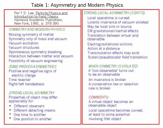
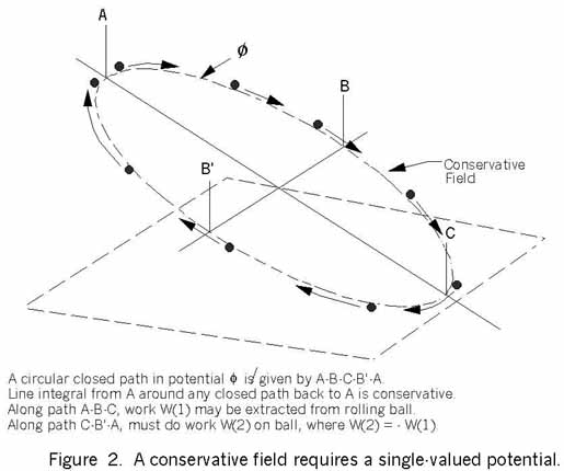
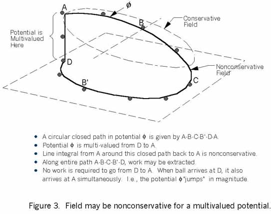
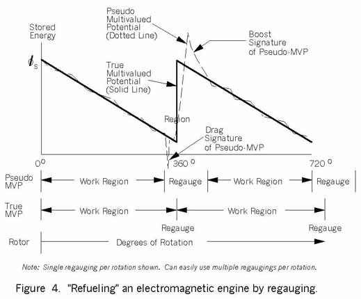
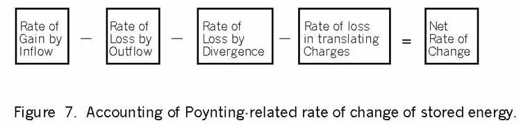
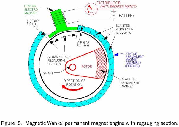
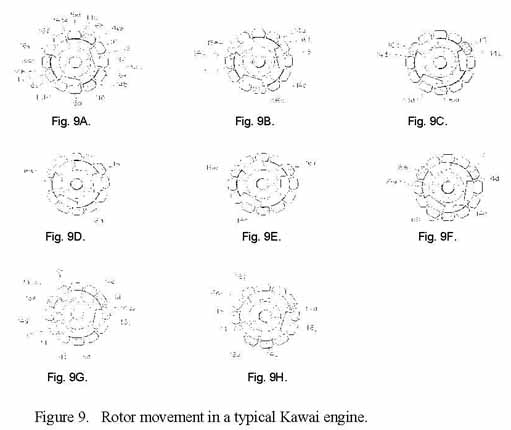